Welcome: Shenzhen Midoriled co., Limited.
Language:
 ∷
∷

∷
 ∷
∷
Product Specifications
Model number:HC008
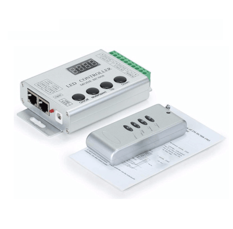
Products name:Aluminum Shell full color magic controller
Product Description
Wireless Symphony LED Controller (HC008) is suit for UCS1903 (TM2801 etc) output applications to drive LED directly. It is widely used in advertising, stage sets, home decorations, etc. It has many advantages such as low price, easy connection and simplicity to use. It has a memory function. Meanwhile, you could adjust brightness, static color choices and various dynamic changes in lighting effects through wireless remote control. It can also be used as a synchronous controller. That is to say you can synchronously control number of decoders and LED lights.
Technical Parameters
|
Working temperature |
-20-60℃ |
|
Supply voltage |
DC5V-24V |
|
Current |
<60mA |
|
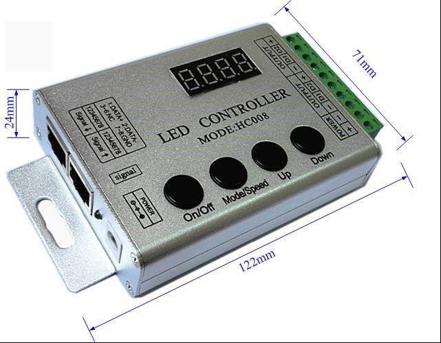
External dimension |
L122xW71×H24mm |
|
Packing size |
L137*W80*H55mm |
|
Net weight |
180g |
|
Gross weight |
270g |
|
Effects model |
133 |
|
Maximum control points |
1024 (Low-speed) points, 2048 (High-speed) points |
|
Controlled IC Model |
Such as the TM16726,TM2801,TM8806,WS2811, UCS1903 etc. (specify the required model on orders) |
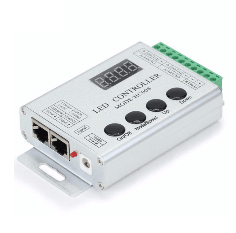
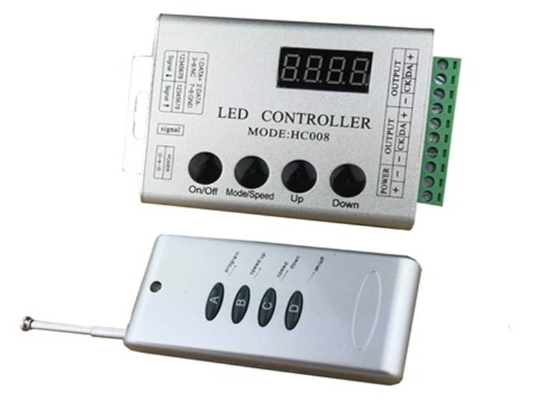
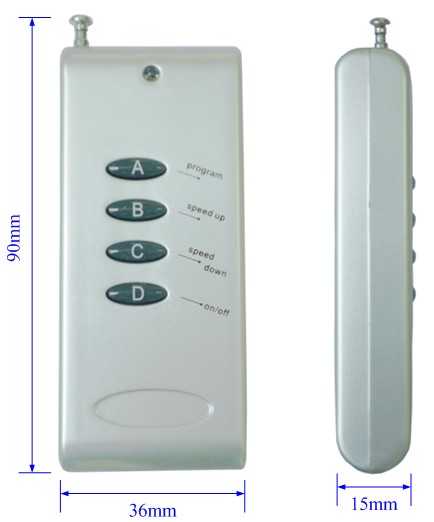
External Dimension
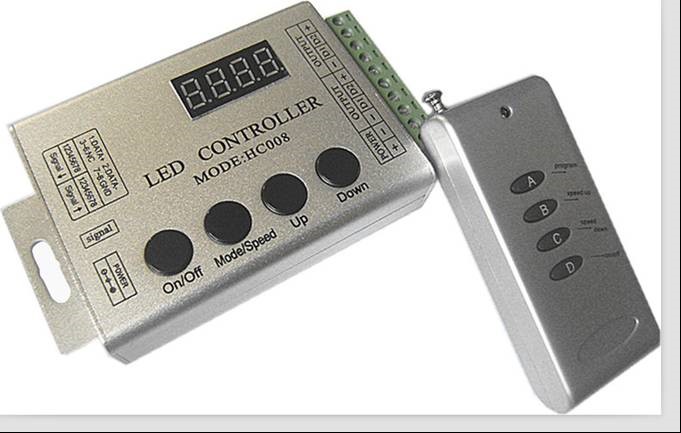
(Controller) (Remote control)
Interface Specifications
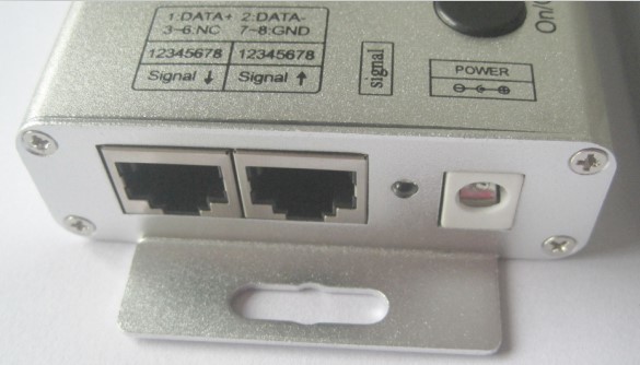
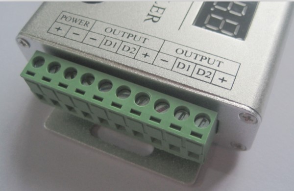
Power input:Adopt DC plug seat connector Load output:Adopt the 10 units of plug seat with screw.
Synchronization interface:
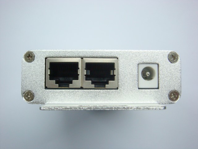 Adopt
Standard network line interface.
Adopt
Standard network line interface.
Direction for use
Connect the load wire at first, following by the power wire; Please ensure short circuit can not occur between connecting wire before you turn on the power. Then set the steps as follows.
Press the "On / off" button to take the controller off before setting the menu.
Press the “up”, “down” button one time at the time, and LED would be bright at this moment. Then press the "Mode / Speed" button to get into the menu settings screen.
The first setting screen is for “High-speed, low-speed settings”, and the LED would display "S-HI" or "S-LO". Then press the “up” and “down” button to select the mode. (If the IC on the light bar is high-speed mode, you should choose “S-HI”, and choose “S-HI” when low-speed.) The factory default is for the high-speed mode.
Continue to press the "Mode / Speed" button to enter the second screen-“Control points setting”. The LED display 4-digit is for the number of control points. To plus or minus the number by pressing the “up” and “down” button (Long pressing can adjust quickly). The factory default is for 50.
After setting well, press the "On / off" button to save and exit.
There are 4 buttons in total on the control panel, function of each button as below:
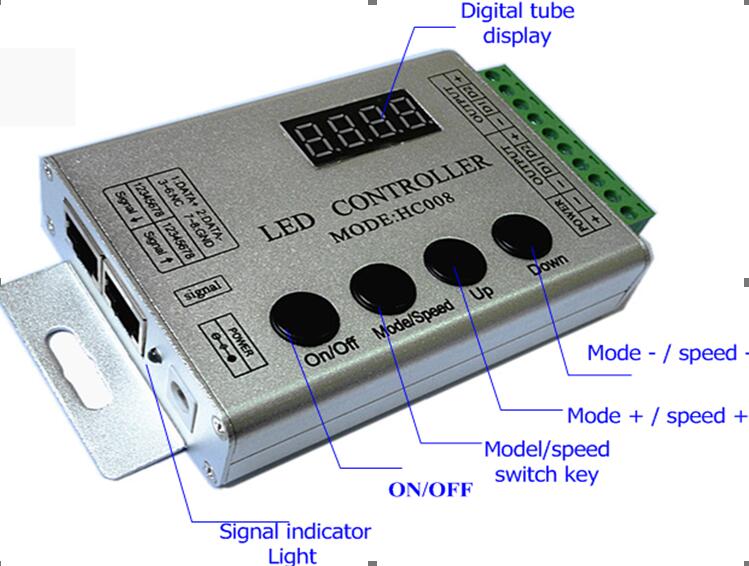
On/off:It can turn on or turn off the output..
Mode/Speed :Mode adjustment / speed adjustment function switch (The first LED displays H for model adjustment, shows S for the speed adjustment.)
UP:Mode+/Speed+ button. When in mode regulator function, it is for “Mode+”. When in speed regulator function, it is for “Speed+”.
DOWN:Mode-/Speed- button. When in mode regulator function, it is for “Mode-”. When in speed regulator function, it is for “Speed-”.
Remarks:When power the controller, the red indicator light will be light up, and the green indicator light will be flash when press the button each time.
Adopt wireless control method, 4keys in total, function of each key as below::
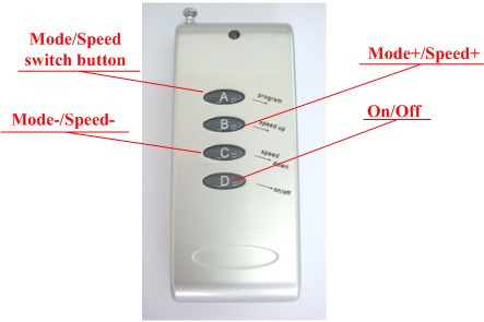
A: Mode adjustment / speed adjustment function switch (The first LED displays H for model adjustment, shows S for the speed adjustment.)
B:Mode+/Speed+ button. When in mode regulator function, it is for “Mode+”. When in speed regulator function, it is for “Speed+”.
C:Mode-/Speed- button. When in mode regulator function, it is for “Mode-”. When in speed regulator function, it is for “Speed-”.
D:On/Off button: It can open or close output.
Remarks:When power the controller, the red indicator light will be light up, and the green indicator light will be flash when press the button each time.
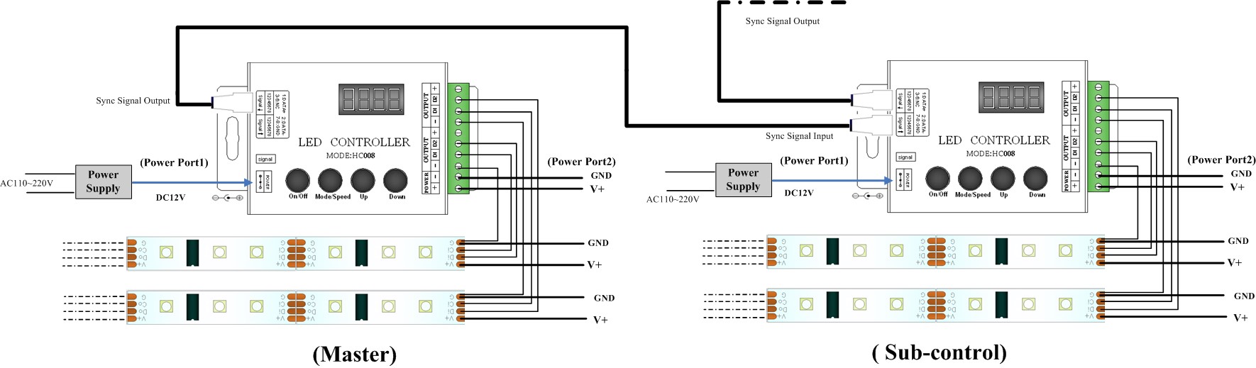
Synchronous controller system description
Synchronous control system can be made of any number of controller connections. Each of the sub-controller would follow to the first master controller to achieve a permanent synchronous change. And there is not delay.
After connecting the wiring diagram, the sub-controller need not be set. It will be in accordance with the master to controlling the speed and mode change. (That would be not synchronous when powering. You could close and open to be synchronous) When master is working, and the sub-control working well, the green signal light of sub-control would flick. The digital LED display the mode in operation.
●The 133th Changing mode (Custom combination mode) operation specification:
This Mode is an editable combination mode, you can edit 2 ~ 20 scenarios (1 to 132 of the pattern) combined into a cycle patterns, each pattern can set change speed separated,can identify the model number and play cycle automatic .
In the OFF station, press the “Mode/Speed”、“Up”two button at the same time then to enter the edit menu,the digital show “-01-”,“-**-”,it means that at this moment can press the “+”、“-”button to edit the scene number.
(2)After setting the scene number,press the “Mode/Speed” for one time , the digital tube will show “H***”,and enter the scene setting state,at this moment can press “+”、“-” button to edit the scene changing function,and the effect of the scene can be seen by the led lights.When the digital show “H000”means that the scene still not be set.
After setting Mode,press the Mode/Press button again,the digital tube will be show “S0*”,Its to show the Speed of the current scene Mode,at this time can adjust the changing speed by press Button “+/-”,and this effect can be seen through the led strips.
After chose the Changing speed,press the “Mode/Speed”button again to enter the scene number setting state“-**-”,at this time can enter another scene and edit it or press the the “On/Off”button to save your choice .
Note: when setting the scene less than 20 kinds, the scene is to start from the first scene (because the 133th mode starts running scene "01"), the scene has not be set the scene mode please set to "H000". If you need to set up five scenarios into 133 model, after entering the edit menu editor "01" to "05" scenario respective model and speed (edit can be not follow order), after edited needs to be checked the "06" scene mode is "H000" or not, if not please press the "+", "-" button to adjust it.
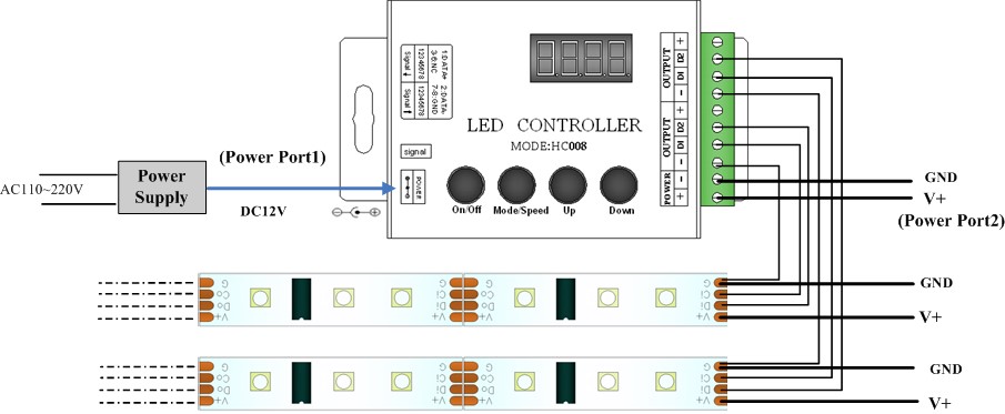
Typical Applications
Application Circuit1:
Application Circuit2:Multi-motor synchronization function application:
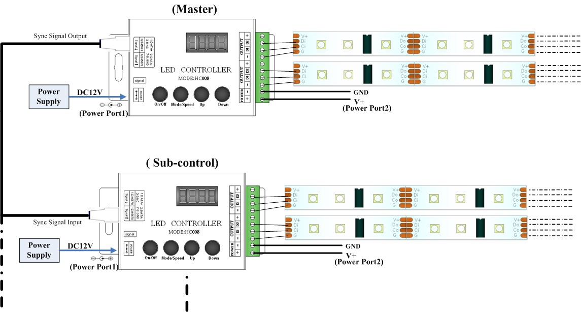
( b.Bus connection,all branch controller’s signal output are from the master controller directly.)
![]() Cautions:
Cautions:
This products Input voltage is DC5V-24V,other input voltage are not allowed.
Lead wire should be connected correctly,according to the wire color and the connecting diagram offers.
Overload are prohibited.
Contact:
Phone: 0086-13510950241
Tel: 0086-755-21055140
Email: info@midoriled.com
Add: 6F,Building B,No.136,Baigongao Industrial Zone, GuanlanTown, Shenzhen City,Guangdong Province,China
 midoriled